The basic sides of the module are made from 1/2 inch birch plywood while the endplates have to be made from 3/4 inch thick material (birch plywood in my case). All is held together with Gorilla glue and some #8 woodscrews.
In March of 2014 I started on my 'chainsaw' Free-mo module project. It is going to be a module featuring a plate girder bridge and a small cut through a hill as found on the old Southern railroad line (now part of Norfolk & Southern's Chesapeake and Western division) that runs behind my house.
One of the goals of this Free-mo module is to explore various building methods that will result in, what I feel, "strong enough" modules to withstand frequent moves in cards and the rough handling at shows. I want the module to be lightweight, yet sturdy enough. I also want to use this module to get a feeling of making scenery: Virginia style hills, rock faces, grass, static grass, trees, scratch build bridges, weathering rails, weathering railroad ties, ballasting and anything else that comes along.
As you can see, a true chainsaw type goal for this module build. Follow along!
The basic sides of the module are made from 1/2 inch birch plywood while the endplates have to be made from 3/4 inch thick material (birch plywood in my case). All is held together with Gorilla glue and some #8 woodscrews.
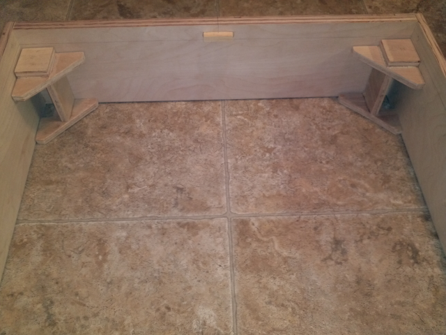
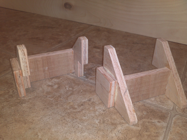
A test fitting of the leg support brackets in 2 of the corners
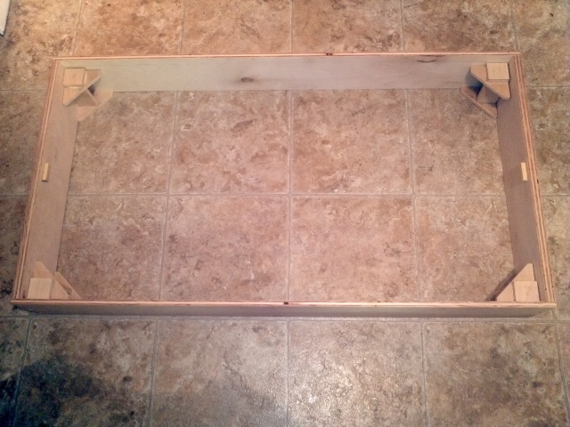
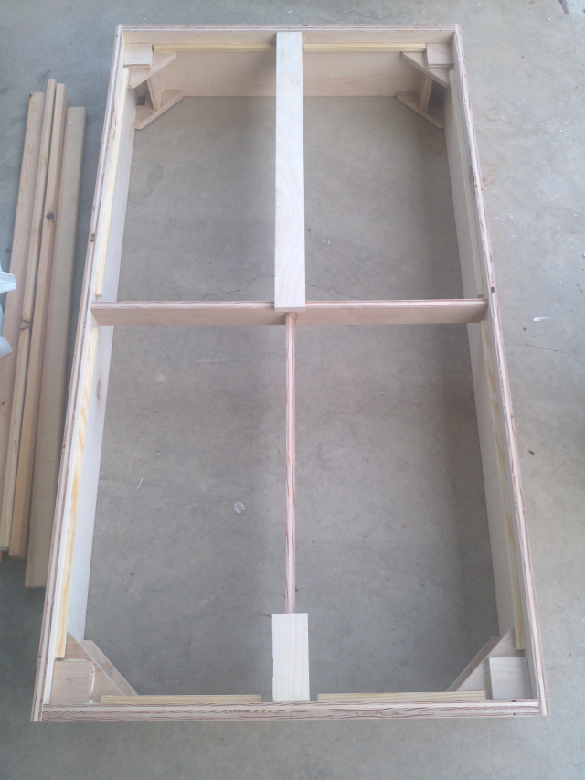
This is what the module should look like (seen from the top) with all 4 leg support brackets glued in place.
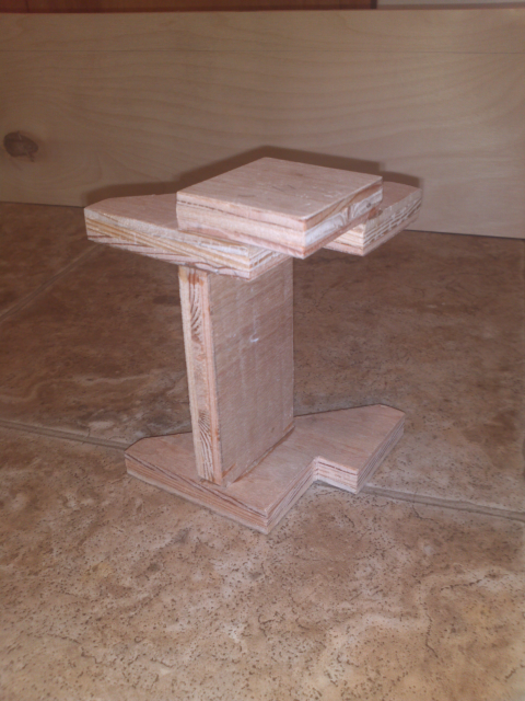
A closeup of one of the leg support brackets I envisioned, completely madfe out of 1/2 inch birch plywood.
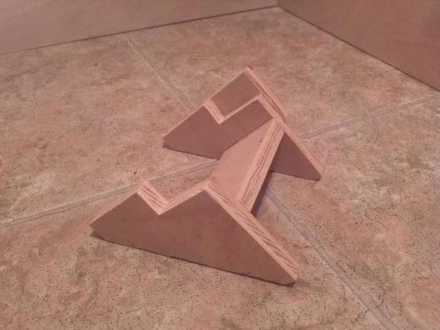
A different angle of the leg support bracket
A pair of mirror image leg support brackets
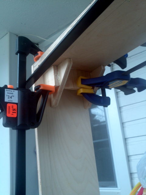
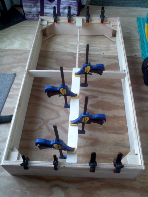
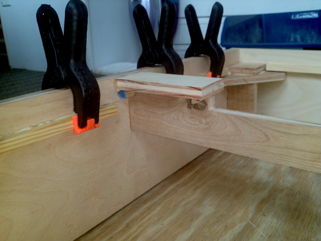
Time to attach the leg support brackets. You can't have enough clamps ever: of course I ran out, so I had to do them in stages of 2 at a time.
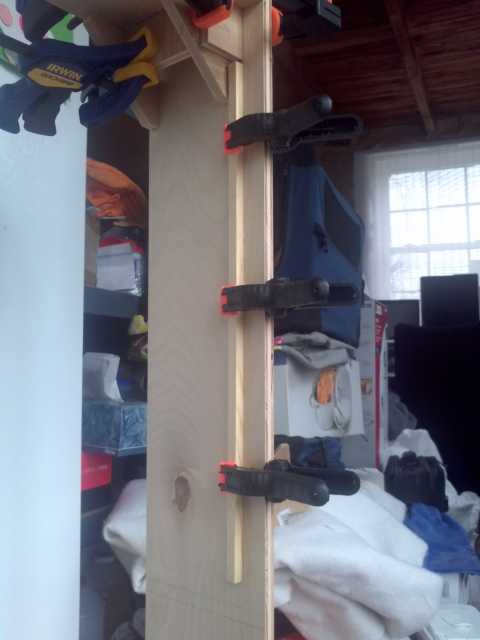
Here I'm glueing in place some 3/8 inch dowels as the support for the 1 inch foam top. All sides of the module will get these dowels glued in place to help adhere the foam to the sides and endplates of the module.
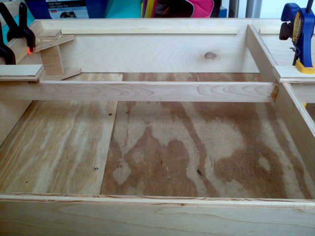
The vertical roadbed support structures, made from 1/2 inch birch plywood, were glued in place. The top vertical support has a 1/2 inch cut out over a length of 17 inches where the bridge will be.
The short piece of roadbed on the far end of the module has been glued in place already, now it's time to glue the final piece of roadbed to the vertical support. Roadbed is made of, you guessed it, 1/2 inch birch plywood as well.
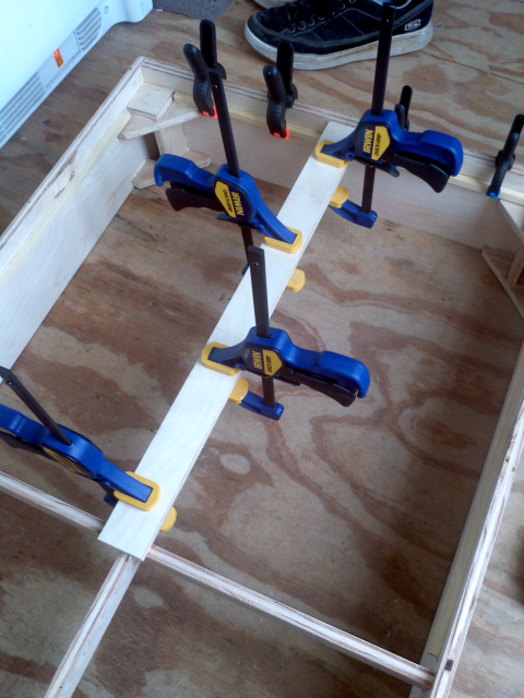
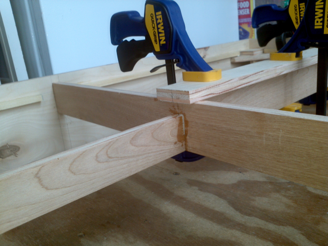
A closeup of the "long" stretch of roadbed being clamped in place while the glue dries.
This is the side view of where the bridge will end up. I compressed the bridge length a bit by making my bridge use only 6 spans versus the prototype using 7 spans of around 20 feet each.
Closeup of the left side of the bridge.
Closeup of the right hand side of the bridge.
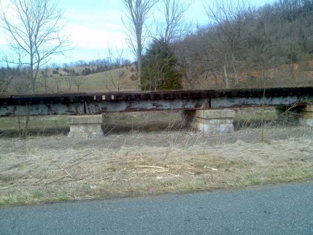
I shouldn't forget to post a prototype picture of the bridge which I'm going to try and scratch build. Don't mind the quality of the pictures, it was cold outside, so I didn't want to leave my warm car. Call me lazy, at least I'm not armchair modelling anymore :)
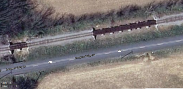
A Google maps overview of the trestle and surrounding area.
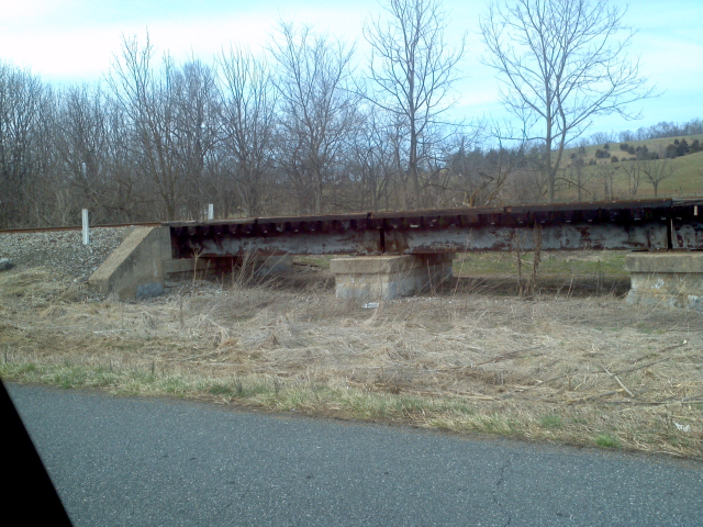
Closeup picture of the bridge #1.
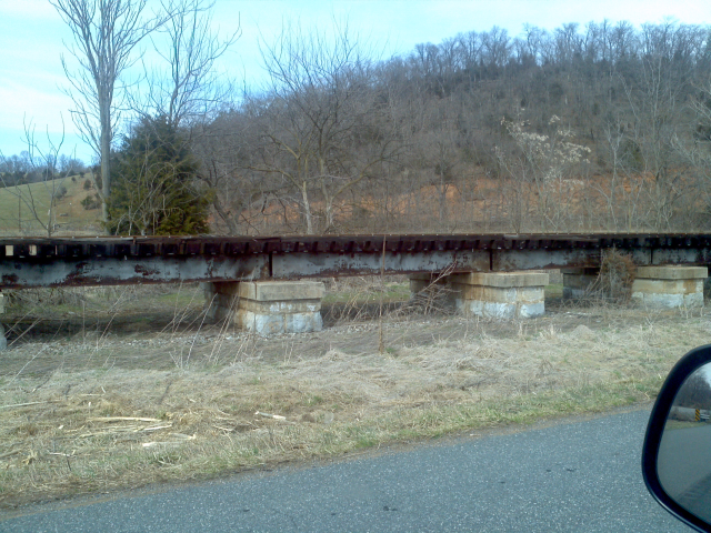
Closeup picture of the bridge #2.
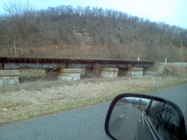
Closeup picture of the bridge #3.
Closeup picture of the bridge #4.
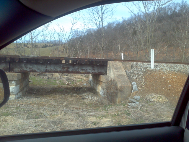
Closeup picture of the bridge #5.
Progress up to April 4, 2014:
The whole module is glued togetheer, including the road bed support
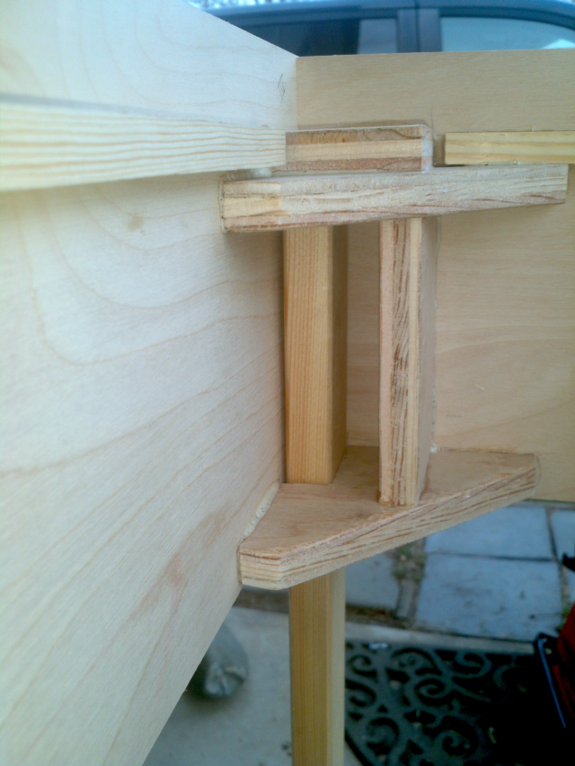
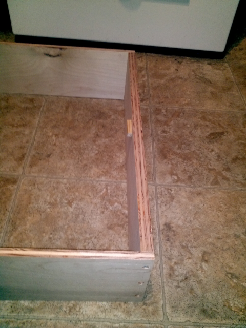
Closeup of the leg support pocket, with a 1x2 leg inserted.

The leg fits in the pocket, but it's kind of tight. I'll need to widen the pocket just a bit to account for expansion of the leg's wood.
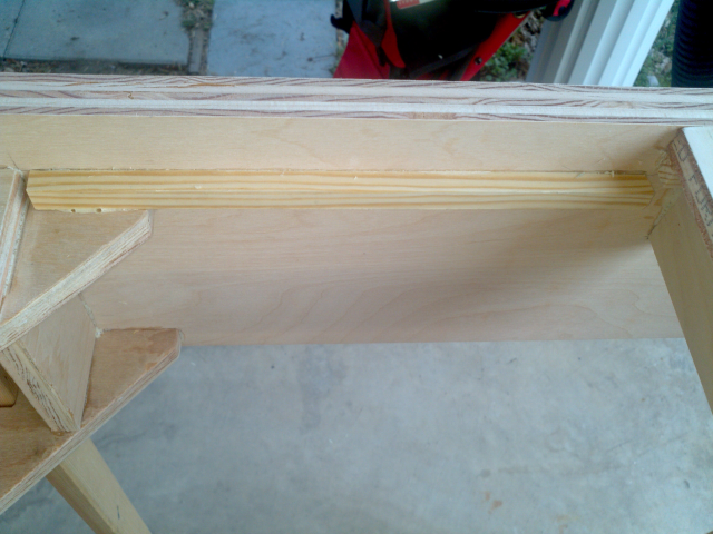
Closeup of one of the foam support ridges, made from 3/8 wooden dowels.
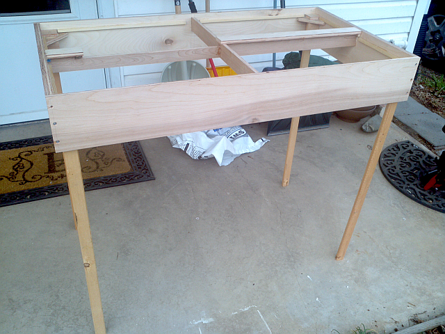
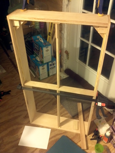
And here it is, the module on its own legs. Second part of the legs will be cut soon and 4 inch leveler plus bracket will be attached. Plan is to allow the module to be at NMRA 40 inches nominal height, all the way up to Free-mo maximum nominal height of 62 inches. By allowing the two pieces of the leg to be adjusted up and down in 3.5 inch increments combined with the use of the 4 inch leveler feet, the module should be able to reach any height between 39 inches to 63 inches floor to top of railhead. All I need is a few minutes worth of time on a drillpress :)
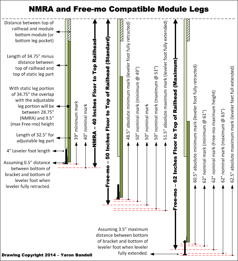
Since a picture says more than a thousand words, here a drawing of the NMRA verus Free-mo module height. All it is missing is the distance / positioning of dril holes to keep the two leg halves together.
Text, images (except Google map image) and code all ©opyright 2014 Yaron Bandell.